Summer Sale - free shipping on all orders!
Personal menu
Search
Blog archive
RSS

Blog

How to Repair Mercedes Axor II ECU?

How to Repair Mercedes Axor II ECU?

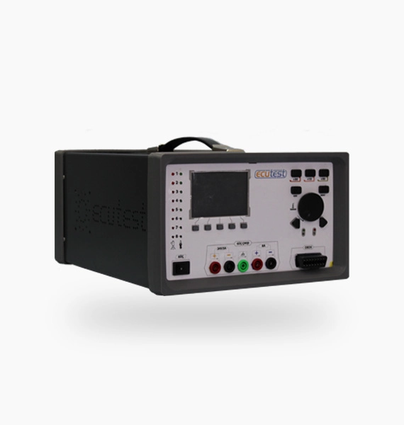
Ecutest Ecu Simulation and Test Device, Thermal Camera (Optional), multimeter and soldering iron set were used for Mercedes Axor II- 2013 Model-Diesel-6 Cylinder-EURO 5 vehicle whose Ecu name was TEMIC WDF375.4 NMB375.4. (Ecu Repair)

The heavy vehicle owner called our garage and reported that the engine did not start despite the heavy vehicle cranking, the crankshaft sensor had changed before calling us, the sensor’s socket and wiring were intact, but the vehicle still did not work, saying that he thought the problem would be in the engine Ecu.

We said that the failure of the vehicle even though there was no problem in the sensor, its socket and the wiring indicated that the problem was in the engine Ecu, and we took the engine Ecu to the desktop by asking the customer.

Mercedes Axor II Ecu Repair

A connection was made between the pins of TEMIC WDF375.4 NMB375.4 Ecu belonging to Axor II-EURO 5 and Ecutest Ecu Simulation and Test Device on the desktop.

You can make this connection with the help of the socket belonging to the TEMIC WDF375.4 NMB375.4 Ecu or with the help of the Unıversal Cable that allows you to connect easily to all the vehicles provided with ECUTEST device.

We made the connection with our Universal cable and ran the ECUTEST program on our computer. After selecting the vehicle brand and model, our simulation screen was opened.

When our simulation screen was opened, we first checked the supply voltages to the sensors by clicking the ‘Sensor Powers’ button on the left and observed that it was okay.

Ecu Test

When we returned to our simulation screen, we found very easily both on the screen and on the Ecutest Ecu Simulation and Tester that the crankshaft sensor did not send a correct signal to the Ecu, so the firing times of the injectors were irregular.

After detecting that the crankshaft sensor was defective, we clicked the ‘Component Description’ button at the top of our simulation screen to see the integral to which the crankshaft is connected, then exit from here and click on the ‘ECU Electrical Diagram’ to learn the pins connected to the crankshaft and check the path of the pins and there is a problem on the road.

Was checked with the help of a multimeter. When we checked the integrated crankshaft with a multimeter, we found that the integrated legs were short-circuited to each other, and when we looked with a thermal camera, it was much higher than normal and lost its function with both the multimeter and the thermal camera.

It was observed that the integrated function that manages the crankshaft does not allow the sensor to work correctly, and therefore affects the injectors.

By removing the integrated that manages the crankshaft with the soldering iron equipment without damaging the ECU, a solid integral was placed in its place. After replacing the integrated, we reconnected the Ecu to the Ecutest Ecu Simulation and Test Device.

We have seen that the crankshaft works smoothly and fires the injectors regularly, both on the simulation screen and on the device.

In this way, the failure of the TEMIC WDF375.4 NMB375.4 Ecu on the table without the vehicle was easily resolved with the Ecutest Ecu Simulation and Test Device at the lowest cost and with the exact solution, and the Ecu was delivered to the customer.

Mercedes Atego ECU Repair

Mercedes Atego ECU Repair

The owner of 2012 Model Mercedes ATEGO EURO 5 heavy vehicle called our garage and said that his vehicle did not move and gave an error (Mercedes ATEGO Ecu Repair).

Since the problem is in the ECU, we asked him to disassemble the ECU and send it to us. We have taken the engine Ecu of Mercedes ATEGO heavy vehicle TEMIC OM906 to the desktop.

How to Repair Mercedes ATEGO ECU (TEMIC OM906)?

We connect the TEMIC OM906 engine Ecu to the Ecutest Ecu Simulation and Test Device. We made this connection with the Universal Socket, which is provided when you buy the Ecutest Ecu Simulation and Test Device, which allows you to easily connect to all heavy vehicle and passenger engine Ecu .

At the request of our customers, we make it in the original socket of each engine Ecu , so you can directly plug the socket to the ECU and make your connection.

After we make our connection, we pain our simulation of the Ecutest Ecu Simulation and Test Device from the computer. After selecting the vehicle brand and model, we approve the Mercedes ATEGO, ECU TEMIC OM906 and enter our simulation screen.

We run the TEMIC OM906 on our simulation screen and first click the “Sensors Powers” button on the left to check the supply voltages of the sensors and see that there is no problem.

Ecu Test

We check the sensor values ​​of TEMIC OM906 on the right side of our simulation screen. The Ecutest Ecu Simulation and Tester allows us to increase and decrease the values ​​of the sensors so that we can see if the sensor is working correctly.

We move forward by changing the sensor values ​​and we see that there is only a malfunction in the AdBlue Temperature Sensor (AdBlue Temperature Sensor) with a red light on the simulation screen.

Because the defective sensor, valve or injector on the simulation screen fails as a red light. The AdBlue problem code, which is a chronic problem of heavy vehicles, prevents the vehicle from moving. In order to move your heavy vehicle, you first need to solve this problem.

We open the inner diagram of TEMIC OM906 by clicking the “Component Description” button at the top of our simulation screen. Here, we can see which integrated does what, its brand and model on the screen. We find the circuit element to which the AdBlue Temperature Sensor is connected.

Then we see the pins connected to the “Electric Diagram” to the AdBlue Temperature Sensor. Then, with the help of a multimeter, we first check the path of the pins and see that there is no problem.

When we examine the circuit element they are connected to, we see that it has lost its function and is defective. With the help of a soldering iron, we remove this circuit element without damaging the ECU and replace it with the solid circuit element.

We are reconnecting the TEMIC OM906 ECU to the Ecutest Ecu Simulation and Ecu Repair. When we run our simulation screen, we observe that the problem has been resolved and on the simulation screen.

Thus, with the Ecutest Ecu Simulation and Testing Device, we solve the TEMIC OM906 ECU of the Mercedes ATEGO EURO 5 vehicle quickly, easily and with minimum cost.

Mercedes Tourismo ECU Repair

Mercedes Tourismo ECU Repair

The owner of the Mercedes Tourismo Euro 5 motor passenger bus called our garage and said that his vehicle had just changed Adblue, but it gave an Adblue problem on the screen (Mercedes Tourismo Ecu Repair).

We said we would help if he sent the ECU to us. Then we took the vehicle’s ECU to the desktop.

How to Repair Mercedes Tourismo ECU?

We are starting to examine the TEMIC OM457HLA ECU of the Mercedes Tourismo vehicle on the desktop. First of all, we make a connection between TEMIC OM457HLA and Ecutest Ecu Simulation and Test Device.

We made this connection with the Universal Socket, which is provided with the Ecutest Ecu Simulation and Test Device, allowing you to easily connect to all heavy vehicle and passenger engine Ecu .

Upon the request of our customers, we can make it in the original socket of each engine Ecu , so you can connect the socket directly to the ECU and make your connection.

After making our connection, we open our simulation of the Ecutest Ecu Simulation and Test Device from the computer. After selecting the vehicle brand and model, we approve the ECU TEMIC OM457HLA and enter our simulation screen.

When we run our simulation screen, we first check the sensor supply voltages by clicking the “Sensors Powers” button on the left side of the screen. When we look at it, we see that it is unproblematic.

Later, we see that the “AdBlue Heater Valve” AdBlue Heater Valve, which appears in the middle of the screen, is defective and has malfunctioned in the red light.

Ecu Test

Thus, we find the problem of TEMIC OM457HLA ECU. After finding the fault, we first see the internal diagram of the TEMIC OM457HLA ECU by clicking the “Component Description” button on our simulation screen.

Here it is written the role and brand of the circuit elements. Here we find the circuit element that controls the AdBlue Heater valve. Then, by clicking on ‘Electric Diagram’, we see the pin ends and signal types that the AdBlue Heater valve is connected.

Thus, thanks to the Ecutest Ecu Simulation and Test Device, we learn both the circuit element and the pin ends. Then we examine the integrated integrated with the help of a multimeter and see that there is no problem.

When we follow the path it is connected to from the ECU pins, we notice that there is a disconnection on the road. We repair the road without damaging the ECU. After this process is over, we connect the TEMIC OM457HLA Engine Ecu back to the Ecutest Ecu Simulation and Test Device.

We do our test on our simulation screen and observe that the problem has been resolved and the valves are working smoothly.

Thus, thanks to the Ecutest Ecu Simulation and Test Device, we can solve the TEMIC OM457HLA ECU’s problem in the fastest, easiest and lowest cost. We deliver the TEMIC OM457HLA ECU to our customer.

Mercedes Travego Engine ECU Repair

Mercedes Travego Engine ECU Repair

The owner of the Mercedes Travego 2014 Model EURO 5 Motor vehicle called our garage and reported a malfunction in the ECU. We have taken the TEMIC OM457 ECU to the desktop (Ecu Repair).

How is Mercedes Travego Engine ECU Repair Performed?

We made a connection between the ECU, which is the TEMIC OM457 belonging to Mercedes Travego, and the Ecutest Ecu Simulation and Test Device.

We made this connection with the Universal Socket, which is provided when you buy the Ecutest Ecu Simulation and Test Device, which allows you to easily connect to all heavy vehicle and passenger engine Ecu.

Upon the request of our customers, we can make it in the original socket of each engine Ecu, so you can connect the socket directly to the ECU and make your connection.

After we make our connection, we pain our simulation of the Ecutest Ecu Simulation and Test Device from the computer. After selecting the vehicle brand and model, we confirm the ECU TEMIC OM457 and enter our simulation screen.

When we run our simulation, we can see that the injectors are working smoothly both on the screen and on the device. Then we check the sensor supply voltages from the “Sensors Power” button on the left and see that it is OK.

When we check the sensors with the Ecutest Ecu Simulation and Test Device, which allows us to change the values of the PRESSURE-LEVEL-TEMPERATURE sensors on the right, we see that the “SCR Pressure Sensor” warns as a red light that it is defective.

Ecu Test

We see that other sensors are working without any problems. With the Ecutest Ecu Simulation and Test Device, we quickly and easily detected the failure of the TEMIC OM457 ECU. We open the TEMIC OM457 inner schema by clicking the ‘Component Description’ button at the top of our simulation screen.

Here, we can see which integrated does what, its brand and model on the screen. We see that the SCR Pressure sensor is connected to the microprocessor.

By clicking ‘Electric Diagram’, we see the ECU pins connected to the SCR Pressure sensor. First of all, we check the path from the ECU pin to the circuit element with a multimeter. We see that there is a disconnection on the road and that it did not complete the circuit.

Then we complete this path with the help of a soldering iron. We test the TEMIC OM457 by connecting it to the Ecutest Ecu Simulation and Tester again and this time we see that the SCR Pressure Sensor is working without any problems.

Thus, with the Ecutest Ecu Simulation and Testing Device, we solve the TEMIC OM457 ECU of the Mercedes TRAVEGO EURO 5 vehicle quickly, easily and at minimum cost.

Continental SIMOS PCR 2.1 Ecu Repair

Continental SIMOS PCR 2.1 Ecu Repair

Ecu Repair-Ecu Name: Continental SIMOS PCR 2.1

Vehicle Information: Volkswagen GOLF 1.6 TDI-2010

Materials Used: Ecutest Ecu Simulation and Tester, multimeter and soldering iron set

2010 model Volkswagen Golf vehicle came to our garage and it was learned by the customer that the Ecu on the vehicle was defective. First of all, we disassembled the Ecu from the vehicle and took it to the desktop.

A connection was made between the pins of the Continental brand PCR2.1, which belongs to the vehicle, and the Ecutest Ecu Simulation and Test Device on the desktop.

You can make this connection by means of the socket belonging to the PCR2.1 computer or by using the unıversal cable that allows you to connect easily to all the vehicles provided with the ECUTEST device.

We made the connection with our Universal cable and ran the ECUTEST program on our computer. After selecting the car brand and model, our simulation screen was opened.

Ecu Test

In the simulation screen, the voltage values ​​to the sensors, the rotation values ​​of the crankshaft and camshaft were checked and it was seen that they were OK.

When the speed of the vehicle was increased and decreased with the help of the RPM button on the simulation screen, when the speed of the injectors was checked, it was seen that the injector numbered 3 gave a red fault warning on the simulation screen and the injector number 3 did not fire on the Ecutest Ecu Simulation and Test Device.

The sensor values ​​on the right side of our simulation screen were checked to see if there were any other malfunctions in the Ecu, and it was determined that it was OK.

Thus, we have determined that only the number 3 injector of the Ecu is defective, other sensors are working without any problems, with the help of the Ecutest Ecu Simulation and Test Device, without a vehicle.

First, with the help of the Ecutest Ecu Simulation and Test Device, the pins belonging to the injector number 3 of the Ecu and the circuit element to which it is connected were detected.

Then, with the help of a multimeter, the paths of the circuit element connected to it were checked and it was found that there was no problem.

When we checked the MOSFET, which is the circuit element to which injector number 3 was connected, we saw with the multimeter that it lost its function and that its legs were short-circuited to each other due to the high current.

The defective circuit element was removed with the help of a soldering iron set and a solid mosfet was installed instead.

When we reconnected the Ecu to the Ecutest Ecu Simulation and Test Device, it was seen on both the simulation screen and the Ecutest Ecu Simulation and Test Device that the problem was solved and that injector number 3 did not give a warning and fired normally.

In this way, the malfunction of the PCR2.1 Ecu on the table without the vehicle was easily resolved with the Ecutest Ecu Simulation and Test Device at the lowest cost and with the exact solution, and the Ecu was delivered to the customer.

Peugeot 307 ECU Repair

Peugeot 307 ECU Repair

The owner of the Peugeot 307 1.6i called our garage and reported that there was a malfunction in the ECU, the engine light turned on on the indicator screen and the vehicle misfired while idling (Ecu Repair).

We said we would help if he sent the ECU to us. Then we took the vehicle’s ECU to the desktop.

How to repair Peugeot 307 ECU?

We start to examine the BOSCH ME7.4.4 Ecu, which belongs to the Peugeot 307 1.6i vehicle, on the desktop. First of all, we make a connection between BOSCH ME7.4.4 and Ecutest Ecu Simulation and Test Device.

We made this connection with the Universal Socket, which is provided with the Ecutest Ecu Simulation and Test Device, allowing you to easily connect to all heavy vehicle and passenger engine Ecu.

Upon the request of our customers, we can make it in the original socket of each engine Ecu, so you can connect the socket directly to the ECU and make your connection.

After making our connection, we open our simulation of the Ecutest Ecu Simulation and Test Device from the computer. After selecting the vehicle brand and model, we confirm the ECU BOSCH ME7.4.4 and enter our simulation screen.

When we run our simulation screen, we first check the sensor supply voltages by clicking the “Sensors Powers” button on the left side of the screen.

When we look at it, we see that it is unproblematic. Later, when we change the values ​​of the sensors on the right, we see that the Throttle Motor Sensor (Throttle Motor) is out of order and it gives a warning in a red light.

Ecu Test Simulator

After finding the fault, we first see the internal diagram of the BOSCH ME7.4.4 ECU by clicking the “Component Description” button on our simulation screen. Here it is written the role and brand of the circuit elements.

Here we find the circuit element that controls the Throttle Motor Sensor. Then click ‘Electric Diagram’ to see the pin ends and signal types connected to the Throttle Motor sensor. Thus, thanks to the Ecutest Ecu Simulation and Test Device, we learn both the circuit element and the pin ends.

With the help of the multimeter, we first check the circuit element connected to the ECU, we see that the circuit element works without any problems.

When we look at the pins of the ECU, we find that they are not connected to the circuit element and that there is a break in the circuit path. Then we complete this disconnection without damaging the ECU.

Then we connect the BOSCH ME7.4.4 Engine Ecu back to the Ecutest Ecu Simulation and Test Device. When we checked again, we observed that the problem was resolved and the ECU was working without any problems.

Thus, thanks to the Ecutest Ecu Simulation and Testing Device, we can solve the problem of the BOSCH ME7.4.4 ECU in the fastest, easiest and lowest cost. We deliver the BOSCH ME7.4.4 ECU to our customer.


Renault Symbol Instrument Panel Repair

Renault Symbol Instrument Panel Repair

Renault Symbol 1.5 DCI owner called our garage and reported that there was a problem with the ECU and display of his vehicle(Symbol Instrument Panel Repair).

We asked him to remove the ECU and the indicator of the vehicle and send it to us. We took the SAGEM brand S3000 coded engine Ecu and indicator to the desktop.

Using the Ecutest Ecu Simulation and Test Device, we connected the ECU, which is SAGEM S3000, and the indicator to the device by looking at the pin diagrams.

Ecutest Ecu Simulation and Test Device is the device that allows us to control the ECU and the instrument panel as if we were on the vehicle.

We set up our connection by looking at the schematics loaded in the Ecutest Ecu Simulation and Tester and run our simulation by powering 12V.

Since the Ecutest Ecu Simulation and Testing Device is a test device that provides the opportunity to adjust the firing time of the sensors, valves, injectors inside the ECU and the firing times of the ignition coils, our job is very easy. We have observed the change in the display by running our simulation screen and playing with the sensor values.

ecutest-ecu-test-simulator

As a result of this observation, we saw that when we changed the value of the ECT (Engine Coolant Temperature Sensor), which is the Engine Coolant Temperature Sensor, on the Ecutest Ecu Simulation and Test Device simulation screen, there was no change in the display of the vehicle.

Thus, we have determined that the problem is not in the ECU, but in the indicator. When we opened the back of the indicator, we examined the needle showing the engine temperature affected by the ECT.

When we examined the way to the needle indicating the engine temperature, we found that the diode exploded, did not transmit power and consequently prevented the correct operation of the needle indicating the engine temperature.

With the help of a soldering iron, we carefully remove the defective diode, which has lost its function, without damaging the indicator. We carefully replace the solid diode.

We check the disassembly and assembly process we made with the help of the multimeter and see that it is okay.

When we connected our indicator and ECU back to the Ecutest Ecu Simulation and Test Device, we observed that the indicator also changed when we changed the value of the Engine Coolant Sensor.

When we checked the other sensors, we found that there was no problem, they were working without any problems.

Thus, thanks to the Ecutest Ecu Simulation and Testing Device, we tested both the ECU and the Instrument Panel very easily and in the shortest time. Later, we delivered the ECU and the Instrument Panel to our customer.

SCANIA R400 Engine ECU Repair

SCANIA R400 Engine ECU Repair

The owner of the Scania R400 2015 model heavy vehicle called our garage and reported that his vehicle turned on a fault light and the injectors did not stop even when the engine was turned off (Scania R400 2015 Ecu Repair). We wanted to disassemble the ECU and send it to us.We took the TEMIC-1917800 ECU to the desktop.

How is SCANIA R400 Engine ECU Repair Performed?

We made a connection between the engine Ecu, TEMIC-1917800, which belongs to the Scania R400 heavy vehicle, and the Ecutest Ecu Simulation and Test Device.

We made this connection with the Universal Socket, which is provided when you buy the Ecutest Ecu Simulation and Test Device, which allows you to easily connect to all heavy vehicle and passenger engine Ecu.

Upon the request of our customers, we can make it in the original socket of each engine Ecu, so you can connect the socket directly to the ECU and make your connection.

After making our connection, we open our simulation of the Ecutest Ecu Simulation and Test Device from the computer. After selecting the vehicle brand and model, we approve the ECU TEMIC-1917800 and enter our simulation screen.

When we open our simulation screen, we look at the injectors and observe that it is okay. Then we check the sensors on the right. The Ecutest Ecu Simulation and Test Device allows us to change the values of the sensors connected to TEMIC-1917800.

By changing the sensor values, we understand that the sensor is without any problem in the harmony between the value we assign to the sensor and the value given to us by the sensor.

We lower and raise all sensor values and we see that only the “Fuel Temperature Sensor” is defective and it lights up as a red light on the simulation screen.

When the Fuel Temperature Sensor fails, the ECU continues to run the engine because it cannot receive a temperature signal from this sensor.

Then, we open the TEMIC-1917800 inner diagram by clicking the ‘Component Description’ button at the top of our simulation screen. Here, we can see which integrated does what, its brand and model on the screen.

ecutest-ecu-test-simulator

We find the circuit element to which the Fuel Temperature Sensor is connected. Then click on ‘Electric Diagram’ and see the pins connected to the Fuel Temperature Sensor.

Then, with the help of a multimeter, we first check the path of the pins and see that there is no problem. When we examine the circuit element they are connected to, we see that it has lost its function and is defective.

With the help of a soldering iron, we remove this circuit element without damaging the ECU and replace it with the solid circuit element. We are connecting the TEMIC-1917800 ECU back to the Ecutest Ecu Simulation and Test Device.

When we run our simulation screen, we observe that the problem has been resolved. Thus, with the Ecutest Ecu Simulation and Test Device, we solve the problem of TEMIC-1917800 ECU of the SCANIA R400 vehicle quickly, easily and with minimum cost.

Seat Leon ECU Repair

Seat Leon ECU Repair

The owner of the Seat Leon 1.6 TDI called our garage and reported that there was a problem in the ECU of his vehicle and the indicator failed. We said we would help if he sent the ECU to us (Ecu Repair).

Then we took the vehicle’s ECU to the desktop.

How to Repair Seat Leon ECU?

We start to examine the SIMOS PCR2.1 Ecu, which belongs to the Seat Leon 1.6 TDI TDI vehicle, on the desktop. First of all, we make a connection between SIMOS PCR2.1 and Ecutest Ecu Simulation and Test Device.

We made this connection with the Universal Socket, which is provided with the Ecutest Ecu Simulation and Test Device, allowing you to easily connect to all heavy vehicle and passenger engine Ecu.

Upon the request of our customers, we can make it in the original socket of each engine Ecu, so you can connect the socket directly to the ECU and make your connection. After making our connection, we open our simulation of the Ecutest Ecu Simulation and Test Device from the computer.

After selecting the vehicle brand and model, we confirm the ECU SIMOS PCR2.1 and enter our simulation screen. We see that the injectors, valves and sensors are okay.

Later, when we checked the sensor supply voltages by clicking the “Sensors Powers” button on the left, we saw that the value should be 5V, but the value was 0V in the red light.

Thus, we found the malfunction of the SIMOS PCR2.1 ECU. Then, by clicking on the “Component Description” button on the top, we see the internal diagram of the SIMOS PCR2.1 ECU. Here it is written the role and brand of the circuit elements.

ecutest-ecu-test-simulator

Here we find the Power Driver Integration. Clicking on ‘Electric Diagram’ we see the 5 V pins of the sensors. Then we check the path from the pins to the Power Driver Integration with a multimeter.

We see that it is seamless. When we test the integrated with the multimeter, we understand that the integrated legs are short-circuited to ground and it has lost its function.

You can also do this with a thermal imager by powering the Ecu. We remove the defective integrated with the soldering iron, without damaging the ECU, and replace it with our solid integral.

After completing this process, we connect our SIMOS PCR2.1 ECU to the Ecutest Ecu Simulation and Test Device again.

We run our simulation again. When we check the sensor supply voltages, we see that the problem is solved, they give 5V output on our simulation screen and we complete our test.

Thus, thanks to the Ecutest Ecu Simulation and Test Device, we can solve the problem of SIMOS PCR2.1 ECU quickly, easily and with minimum cost. We deliver our SIMOS PCR2.1 ECU to our customer.

Skoda Octavia ECU Repair

Skoda Octavia ECU Repair

The owner of the Skoda Octavia 2.0 TDI (Ecu Repair) called our garage and reported that he had just completed all the maintenance of his vehicle, but the vehicle had a fault code.

We said we would help if he sent the ECU to us. Then we took the vehicle’s ECU to the desktop.

Skoda Octavia ECU Repair How?

We start to examine the BOSCH EDC16U1 ecu, which belongs to the Skoda Octavia 2.0 TDI vehicle, on the desktop. First of all, we make a connection between BOSCH EDC16U1 and Ecutest Ecu Simulation and Test Device.

We made this connection with the Universal Socket, which is provided with the Ecutest Ecu Simulation and Test Device, allowing you to easily connect to all heavy vehicle and passenger engine Ecu .

Upon the request of our customers, we can make it in the original socket of each engine Ecu , so you can connect the socket directly to the ECU and make your connection.

After making our connection, we open our simulation of the Ecutest Ecu Simulation and Test Device from the computer. After selecting the vehicle brand and model, we confirm the ECU BOSCH EDC16U1 and enter our simulation screen.

When we run our simulation screen, we first check the sensor supply voltages by clicking the “Sensors Powers” button on the left side of the screen. When we look at it, we see that it is unproblematic.

Then we see that the Exhaust gas recirculation valve (EGR Valve) and the Turbo charge position valve (Turbocharger Wheel Position Valve) in the middle of the screen are not working.

When we check the sensors, we see that there is no problem and they work normally. Thus, we find the problem of EDC16U1 ECU.

After finding the fault, we first see the internal diagram of the EDC16U1 ECU by clicking the “Component Description” button on our simulation screen. Here it is written the role and brand of the circuit elements.

Ecutest

Here we find the circuit element that controls the EGR valve and the Turbo charge valve. Then, by clicking on ‘Electric Diagram’, we see the pin ends and signal types that the EGR valve and Turbo charge valve are connected.

Thus, thanks to the Ecutest Ecu Simulation and Test Device, we learn both the circuit element and the pin ends. With the help of the multimeter, we first of all find the way from the pins of the valves to the circuit element they are connected to, we observe that there is no problem on the way.

Later, when we check the integral that they are connected to in the 2 valves, we see that it is damaged, its legs are lifted, but this can be detected with a multimeter, not visually. With the help of a soldering iron, we remove the defective integrated without damaging the ECU and place the solid one in its place.

BOSCH EDC16U1 Engine Ecu Again Ecutest Ecu Simulation and Test

We connect it to the device. When we checked again, we observed that the problem was resolved and the valves were working without any problems.

Thus, thanks to the Ecutest Ecu Simulation and Test Device, we can solve the problem of the BOSCH EDC16U1 ECU in the fastest, easiest and lowest cost. We deliver the BOSCH EDC16U1 ECU to our customer.