Summer Sale - free shipping on all orders!
Personal menu
Search
Blog archive
RSS

Blog posts of '2024' 'January'

Audi A4 Engine ECU Repair How?

Audi A4 Engine ECU Repair How?

The owner of the 2011 model Audi A4-2.0 engine called our garage and reported that the vehicle had EGR failure (Ecu Repair).

He reported that his vehicle was DPF (Diesel Particulate Filter) cleaned, had its exhaust cleaned, but the problem of the vehicle could not be solved.

After realizing on the phone that the problem of the vehicle was in the engine Ecu, we asked him to remove the engine Ecu and send it to us. We have taken the BOSCH brand EDC17CP14 ECU (Engine Ecu) to the desktop.

Audi A4 ECU Repair?

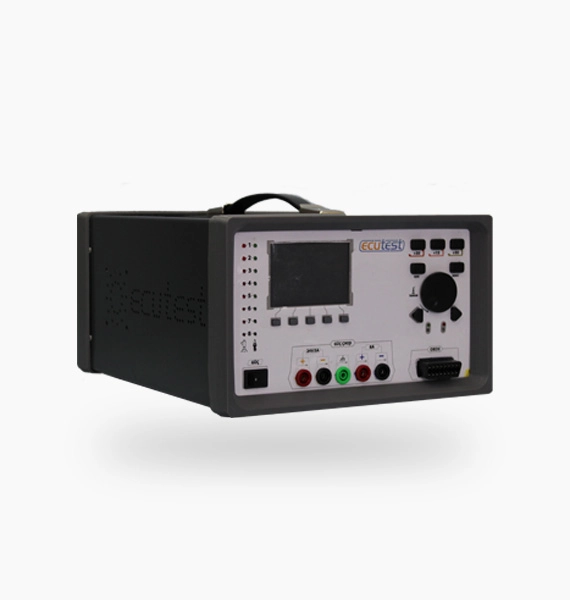
We made a connection between the pins of the BOSCH brand EDC17CP14 ECU and the Ecutest Ecu Simulation and Test Device. We made this connection with the Universal Socket, which is provided when you buy the Ecutest Ecu Simulation and Test Device, which allows you to easily connect to all heavy vehicle and passenger engine Ecu.

Upon the request of our customers, we can make it in the original socket of each engine Ecu, so you can connect the socket directly to the ECU and make your connection.

After we make our connection, we pain our simulation of the Ecutest Ecu Simulation and Test Device from the computer. After selecting the vehicle brand and model, we approve the ECU (Engine Ecu ) EDC17CP14 and enter our simulation screen. When we run our simulation, we see that the injectors fire smoothly.

We check the sensor supply voltages by pressing the “Sensors Power” button on the left side of our simulation screen. We saw that the EGR sensor voltage was 1V when it should have been 5V, as a red light.

Ecu Test

When we look at the section that allows us to change the sensor values on the right side of our simulation screen, we see that the EGR sensor gives a fault warning at the red light. Then, we open the internal scheme of EDC17CP14 by clicking the “Component Description” button at the top of the simulation screen.

When we look at the internal diagram, we see what all the components are for and the brand and model. Then, by clicking on ‘Electric Diagram’, we see the ECU pins to the EGR sensor and which of these pins are ground and which is the supply and which is signal on our Simulation screen.

Thus, we can easily find both the component and the pins in the Ecutest Ecu Simulation and Test Device.
Later, when we checked the component on the ecu to which the EGR sensor was connected, we found that the legs were short-circuited to each other and it lost its function.

With the help of a soldering iron, we remove the defective component without damaging the ECU and carefully place the intact component in its place. In this process, our first priority is not to damage the ECU. After doing these procedures, we connect the EDC17CP14 to the Ecutest Ecu Simulation and Test Device again and open our simulation screen.

When we check the EGR sensor, we see that the fault is gone and there is no problem in the operation of the sensor by changing its value.

Thus, with the Ecutest Ecu Simulation and Testing Device, we solve the problem of Audi A4 BOSCH EDC17CP14 very quickly, very easily and with minimum cost. We deliver the ecu to our customer.

How is Citroen C2 Ecu Repair Performed?

How is Citroen C2 Ecu Repair Performed?

Cıtroen C2-2006 Model-1.6 VTS-Gasoline-Ecu name Ecutest Ecu Simulation and Test Device, multimeter and soldering iron set were used for BOSCH ME7.4.4 vehicle (Citroen Ecu Repair).

The owner of the car, which has a Citroen C2 1.6 VTS engine, called our garage and stated that his vehicle had a Ecu malfunction, the fault lamp on the instrument panel was on and his vehicle did not eat gas. We took the Ecu from our customer and moved it to the desktop.

Citroen C2 Ecu Repair

First of all, we are doing the necessary studies for the Immo-Off process of our vehicle Ecu . After performing the immobilizer shutdown process, we make the connection between ME7.4.4 Ecu and Ecutest Ecu Simulation and Test Device.

You can make this connection with its original socket adapted to Ecutest Ecu Simulation and Testing device belonging to ME7.4.4 Ecu or with a universal cable that you can easily connect to all vehicle Ecu provided with Ecutest Ecu Simulation and Test Device regardless of whether it is heavy vehicle or passenger vehicle.

After making our connection, we open our ECUTEST Simulation on our computer and enter our username and password. We choose the vehicle brand and model. We enter our simulation screen.

First, we check the injectors and ignition coils and see that it is ok. Then, we check the supply voltage to the sensors by clicking the “Sensor Powers” button on the bottom left of our simulation screen.

We see that the Accelerator Pedal Position Sensor supply voltage is colored red and it malfunctions.

When we look at the section that allows us to value the sensors on the right side of our simulation screen, we see on our simulation screen that the signal value we assign to the Accelerator Pedal Position Sensor (APP) is not appropriate and the signal value coming from the Ecu is malfunctioning.

Thus, with the Ecutest Ecu Simulation and Test Device, we can easily find the malfunction of the ME7.4.4 Ecu .

By clicking on the “Electric Diagram” button on the top of our simulation screen, we can see the pins connected to the defective sensor and the signal types of these pins. Then, by clicking the “Component Description” button, we open the inner diagram of ME7.4.4 Ecu .

Here, we can easily see the circuit board to which our defective sensor is connected. When we check the circuit element on the Ecu with the help of a multimeter, we find that the integrated legs are short-circuited.

With the help of a soldering iron, we disassemble the integrated and install the solid integrated instead of it without damaging the ECU.

Thus, the failure of the BOSCH ME7.4.4 Ecu on the table without being in front of the vehicle was easily resolved with the Ecutest Ecu Simulation and Test Device at the lowest cost and with the exact solution, and the Ecu was delivered to the customer.

Cummins ISM11 Engine ECU Repair

Cummins ISM11 Engine ECU Repair

We took the CM876 coded engine Ecu of the Cummins ISM11 engine to the desktop for repair. First of all, we make a connection between CM876 ECU and Ecutest Ecu Simulation and Test Device.

How to Repair Cummins ISM11 Engine ECU?

We made the connection with the CM876 ECU with the Universal Socket, which is provided with the Ecutest Ecu Simulation and Test Device, allowing you to easily connect to all heavy vehicle and passenger engine Ecu .

Upon the request of our customers, we can make it in the original socket of each engine Ecu , so you can connect the socket directly to the ECU and make your connection.

After making our connection, we open our simulation of the Ecutest Ecu Simulation and Test Device from the computer. After selecting the vehicle brand and model, we confirm the ECU (Engine Ecu) Cummins ISM11-CM876 and enter our simulation screen.

When we run our simulation screen, we first check the ‘Sensor Powers’ sensor supply voltages and see that it is OK. We see that the injectors are working both on the simulation screen and on the Ecutest Ecu Simulation and Test Device.

Ecu Test

When we come over the place that fails in the red light visible under the injectors, we see that it is a “Fuel Shut-Off Actuator”. Thus, we find the malfunction of the CM876 ECU. Then, by clicking the “Component Description” button on our simulation screen, we see the internal diagram of the CM876 ECU.

Here it is written the role and brand of the circuit elements. Here we find the circuit element that controls the Fuel Cut Actuator. Then, by clicking on the “Electric Diagram”, we see the pin ends and signal types that the Fuel Cut Actuator is connected to.

Thus, thanks to the Ecutest Ecu Simulation and Test Device, we learn both the circuit element and the pin ends. First, we check the circuit path from the ECU pin to the circuit element to which the fuel cut-off actuator is connected with a multimeter, we see that it is OK.

After seeing that the circuit is OK, we check the circuit element it is connected to and observe that it has lost its function and its integrated legs are short-circuited to the chassis. With the help of a soldering iron, we remove the defective integrated without damaging the ECU and place the solid one in its place.

After doing our process, we connect the CM876 ECU to the Ecutest Ecu Simulation and Test Device again. We see that there is no problem in the ECU that we open our simulation screen, and we complete our test.

Thus, thanks to the Ecutest Ecu Simulation and Test Device, we can solve the problem of the CM876 ECU in the fastest, easiest and lowest cost. We deliver the CM876 ECU to our customer.

DSG Transmission Ecu Repair

DSG Transmission Ecu Repair

The owner of the Volkswagen Passat 1.6 TDI BlueMotion DSG transmission called our garage and stated that his vehicle had problems with gear shifts, ramps and acceleration (Ecu Repair).

He stated that he was taking the mechanic to the mechanic and suspecting the transmission Ecu that there was no problem with the mechanical parts. We wanted the vehicle to disassemble the transmission Ecu and send it to us.

We took the DSG transmission Ecu to the desktop. We find the schematic of the DSG transmission Ecu with the help of the diagnostic devices and automotive sites that we both sell and use in our garage. Then, thanks to this scheme, we identify the communication pins and power pins.

We supply voltage to the power pins of the DSG transmission Ecu whose pins we have detected. It is very important to identify the power pins of the Ecu because when we apply voltage to the wrong pins, we can blow up all the circuit elements in the DSG transmission Ecu .

Many repairmen say that the vehicle owner needs to install a new transmission Ecu , because the transmission Ecu has an easy malfunction by applying voltage to the wrong pins of the transmission Ecu , and the old one is unusable.

When we watch the components on the circuit with the help of a thermal camera, we see that 2 diodes and 1 mosfet have exploded and other circuit elements are functioning normally.

Since the failure of the exploded circuit elements to fulfill their duties also affects other circuit elements, the vehicle cannot perform gear shifts in a healthy way. Transmission computer cannot send correct signal.

Ecu Test

We remove the diodes and the mosfet from the circuit with the help of a soldering iron without harming the Ecu . First we clean it with solder wire. Then we carefully solder the new diodes and the MOSFET onto the circuit.

We wipe the places that we soldered with thinner or alcohol. We check the legs of the circuit elements that we soldered with the help of a multimeter.

When we look at the thermal imager by re-energizing the Ecu , we see that all components work smoothly and we have tested them. We take the vehicle of the DSG Ecu to our garage and attach the Ecu and go for a test drive.

It seems that there is no problem in shifting and we deliver it to the customer. In this way, we solve the problem of the Ecu in the fastest and most economical way.

What is the ECU?

What is the ECU?

What is the ECU? ECU (Electronic Control Unit) is a system used in vehicles that enables control of all systems. In other words, it means Motor Ecu. It is an electronic system that controls and controls the sensors and parts on the engine and calculates the parameters in the vehicle.

In order to drive a car safely and really get performance from it, it is important to carefully and instantaneously evaluate all of its vehicle’s data. This task is undertaken by the ECU in the vehicle, this is the working principle.

When we look at the internal diagram of the Motor Ecu, we can see that there are integrated circuits, transistors, mosfets, diodes, resistors, capacitors, etc. It consists of circuit elements.

Engine Ecu often differ from vehicle to vehicle. The same Engine Ecu can be used in some different vehicles. This is because vehicles have the same parameter and engine system.

For example: The engine Ecu of VW GOLF 1.6 2006 model vehicle and VW PASSAT 1.6 2010 model vehicle is SIMOS brand PCR2.1. It uses the same engine Ecu in both vehicles. When you compare these engine Ecu, only their software may differ.

We can write more of these examples. It uses the same engine Ecu in some vehicles of Peugeot and Citroen.

Ecu Test

ECU FAILURE and HOW TO REPAIR?

In case of a malfunction in the ECU, various malfunction lamps will light up on the instrument panel. The vehicle will react according to the condition of the fault.

For example, if there is an immobilizer malfunction in our vehicle, a sign with a key on the vehicle will light up on the instrument panel and it will not detect the vehicle’s ignition even though you turn the vehicle’s ignition. First, we need to remove the ECU from the vehicle and get it to the desktop.

In this case, whatever the fault of the vehicle is, first of all, it is necessary to find the pins on the ECU that manage the defective part on the ECU. Then, following the path of these pins on the circuit, it is necessary to find the circuit elements and integral they are connected to.

After finding it, we need to check the circuit elements it is connected to and our integration. We need to remove the circuit element or integrated that we see as defective with the help of a soldering iron without damaging the ECU, and replace it with the same circuit element or integrated.

At the last stage, we have to test whether we have fixed the malfunction by attaching the engine Ecu to the vehicle.

But when you have the Ecutest Ecu Simulation and Test Device, all the operations for ECU repair are reduced to minimum cost, it gives you speed and allows you to repair it on the desktop very easily without tools.

So how does it do that?

When you connect the ECU to the Ecutest Ecu Simulation and Test Device and open the simulation screen, it shows you the defective sensor or injector with a red light.

It then shows the pins on the ECU to which this fault is connected and the integral to which it is connected. All we have to do is check the integration. When we solve the fault, we can connect the engine Ecu to the Ecutest Ecu Simulation and Test Device and check whether the fault is solved or not.

In other words, you do not need to work in front of the vehicle, you can easily do it on the desktop thanks to the Ecutest Ecu Simulation and Test Device. You can contact us for technical support and assistance.

Bosch EDC7UC31 ECU Repair

Bosch EDC7UC31 ECU Repair

Ecu Repair – ECU Name: BOSCH EDC7UC31
Vehicle Information: FORD CARGO 1846- 2013 Model-Diesel-6 Cylinder-EURO 5
Materials Used: Ecutest Ecu Simulation and Tester, Thermal Camera (Optional), multimeter and soldering iron set

FORD CARGO 1846 EURO 5 heavy vehicle owner called our garage and stated that the heavy vehicle burned 2 times more fuel than the normal fuel consumption and the engine malfunction lamp turned on.

First, we told our customer to leave the vehicle running for 10 minutes and check the engine temperature after 10 minutes or while on the road, and we learned that the engine temperature did not increase.

We told his master to first check the engine coolant temperature (ECT) sensor’s plugs and wiring, and stated that there was no problem with the socket and the wiring.

We detected that the vehicle’s (ECT) engine coolant sensor has a malfunction on the Ecu because the engine coolant temperature sensor signals the engine Ecu that the engine temperature is always low, the engine injectors ignite more, keep it running at high idle and consume more fuel.

On top of that, because the problem is in the engine Ecu , the engine turns on the malfunction lamp. We removed the Ecu of FORD CARGO 1846 from the vehicle and brought it to the desktop.

A connection was made between the pins of the BOSCH EDC7UC31 Ecu belonging to FORD CARGO 1846 and the Ecutest Ecu Simulation and Test Device on the desktop.

You can make this connection with the help of the socket belonging to the BOSCH EDC7UC31 Ecu or with the help of the Unıversal Cable, which allows you to connect easily to all the vehicles provided with the ECUTEST device.

Ecu Test

We made the connection with our Universal cable and ran the ECUTEST program on our computer. After selecting the vehicle brand and model, our simulation screen opens by confirming the BOSCH EDC7UC31 Ecu .

When our simulation screen was opened, we first checked the supply voltages to the sensors by clicking the ‘Sensor Powers’ button on the left and observed that it was okay. We check the Temperature-Position (Level)-Pressure sensors on the right side of our simulation screen.

Ecutest Ecu Simulation and Test Device allows us to easily assign values to these sensors. We can optionally check these values with any diagnostic device that we will connect to the OBD socket input on the front of the Ecutest Ecu Simulation and Test Device.

We observe that the value we assign to the engine coolant temperature (ECT) sensor is different from the value shown on the screen, and the sensor gives a fault warning in red, and we can easily detect the problem with the Ecutest Ecu Simulation and Test Device.

After detecting that the engine coolant temperature (ECT) sensor is defective, we clicked the ‘Component Description’ button at the top of our simulation screen, and we saw the integrated engine coolant temperature (ECT) sensor was connected, then exit here and click the ‘ECU Electrical Diagram’.

The path of the pins was checked by learning the pins connected to the temperature (ECT) sensor, and it was checked with the help of a multimeter that there was no problem on the way.

When we checked the integrated engine to which the engine coolant temperature (ECT) sensor was connected with a multimeter, we found that the integrated legs were short-circuited to each other, and when we looked with a thermal camera, it was much higher than normal and lost its function with both the multimeter and the thermal camera.

It was observed that the engine coolant temperature (ECT) sensor did not allow the sensor to function properly, as it lost its governing integrated function. By removing the integral that manages the engine coolant temperature (ECT) sensor without damaging the ECU with the soldering iron equipment, a robust integral was placed in its place.

After replacing the integrated, we reconnected the Ecu to the Ecutest Ecu Simulation and Test Device. We have seen on the desktop that the engine coolant temperature (ECT) sensor works smoothly, the value we assigned to the sensor and the value it shows are the same, and it works smoothly with the help of the Ecutest Ecu Simulation and Tester.

In this way, the failure of the BOSCH EDC7UC31 Ecu on the desktop without being in front of the vehicle was easily resolved with the Ecutest Ecu Simulation and Test Device with the lowest cost and exact solution and the Ecu was delivered to the customer.

Iveco Trakker ECU Repair

Iveco Trakker ECU Repair

IVECO Trakker -EURO5 heavy vehicle owner called our garage and reported that his vehicle had a malfunction in the ECU. He reported that his vehicle did not move and did not start Iveco Trakker Ecu Repair.

We said we would help if he sent the ECU to us. Then we took the vehicle’s ECU to the desktop.

How to Repair IVECO Trakker ECU?

We are starting to examine the BOSCH EDC7UC31 ECU, which belongs to the IVECO Trakker EURO-5 vehicle, on the desktop. First of all, we make a connection between BOSCH EDC7UC31 and Ecutest Ecu Simulation and Test Device.

We made this connection with the Universal Socket, which is provided with the Ecutest Ecu Simulation and Test Device, allowing you to easily connect to all heavy vehicle and passenger engine Ecu .

Upon the request of our customers, we can make it in the original socket of each engine Ecu , so you can connect the socket directly to the ECU and make your connection.

After making our connection, we open our simulation of the Ecutest Ecu Simulation and Test Device from the computer.

Ecu Test

After selecting the vehicle brand and model, we approve the ECU BOSCH EDC7UC31 and enter our simulation screen. When we run our simulation screen, we see that the injectors are not working.

After checking our connection between ECU and Ecutest Ecu Simulation and Tester, you can see the internal diagram of the BOSCH edc7uc31 ECU by clicking the ‘Component Description’ button at the top of our simulation screen, as there is a Crankshaft Sensor (CKP) and Camshaft Sensor (CMP) that enable the Injectors to fire.

We see. Here it is written the role and brand of the circuit elements. Here we find the circuit element that controls the Crankshaft Sensor (CKP) and Camshaft Sensor (CMP).

Then click on ‘Electric Diagram’ and see the pin ends and signal types connected to CKP and CMP sensors. Thus, thanks to the Ecutest Ecu Simulation and Test Device, we learn both the circuit element and the pin ends.

With the help of the multimeter, we first check the circuit element connected to the ECU, we understand with the multimeter that the circuit element has lost its function and its legs are short-circuited to the ground line.

Then, without damaging the ECU, we remove the broken circuit element and replace it with the solid circuit element. After this process, we connect our ECU, EDC7U31, again to the Ecutest Ecu Simulation and Test Device.

We are testing it and observed that the problem has been resolved, the ECU is working without any problems, the injectors are all working normally.

Thus, thanks to the Ecutest Ecu Simulation and Test Device, we can solve the problem of the BOSCH EDC7UC31 ECU in the fastest, easiest and lowest cost. We deliver the BOSCH EDC7UC31 ECU to our customer.

Jeep Grand Cherokee ECU Repair

Jeep Grand Cherokee ECU Repair

The JEEP Grand Cherokee all-terrain vehicle owner called our garage and reported that there was a problem with the vehicle ECU. We asked him to send his Ecu to us and we asked him if there was a mechanical breakdown in the vehicle(Jeep Grand Ecu Repair).

Our customer stated that there was no mechanical problem, although the oil level was normal in the vehicle, but it gave an oil failure.

How to Repair JEEP Grand Cherokee ECU?

We took the BOSCH EDC15C5 ECU of the JEEP Grand Cherokee off-road vehicle to the desktop. We made a connection between BOSCH EDC15C5 and Ecutest Ecu Simulation and Tester.

We made this connection with the Universal Socket, which is provided when you buy the Ecutest Ecu Simulation and Test Device, which allows you to easily connect to all heavy vehicle and passenger engine Ecu .

Upon the request of our customers, we can make it in the original socket of each engine Ecu , so you can connect the socket directly to the ECU and make your connection.

After making our connection, we open our simulation of the Ecutest Ecu Simulation and Test Device from the computer. After selecting the vehicle brand and model, we confirm the ECU BOSCH EDC15C5 and enter our simulation screen.

Later, when we checked the sensors on the right side of our simulation screen, we observed that the “Oil Pressure Sensor” in the “Pressure Sensor” category was defective and gave us a warning at the red light.

Ecu Test

When we look at our other sensors, we see that there is no problem even though we change their values. Then, we open the BOSCH EDC15C5 inner diagram by clicking the ‘Component Description’ button at the top of our simulation screen.

Here, we can see which integrated does what, its brand and model on the screen. We find the circuit element to which the Oil Pressure Sensor is connected. Then click on ‘Electric Diagram’ and see the pins connected to the Fuel Temperature Sensor.

Then, with the help of a multimeter, we first check the path of the pins. When we follow the path where the pins are connected to the integral, we detect the disconnection in the path with the help of the Multimeter.

These road disconnections can be invisible to the eye. Using a multimeter for this is the healthiest method. Then we complete our way with the help of a soldering iron, we solve our problem.

For testing, we reconnect the BOSCH EDC15C5 ECU to the Ecutest Ecu Simulation and Test Device. When we turn our simulation screen back on, when we check the sensors, we see that the problem has been resolved and the other sensors work normally.

Thus, thanks to the Ecutest Ecu Simulation and Testing Device, we can solve the problem of the BOSCH EDC15C5 ECU of the JEEP Grand Cherokee off-road vehicle quickly, easily and with minimum cost.

Kia Picanto ECU Repair

Kia Picanto ECU Repair

Kia Picanto 1.1 vehicle owner called our garage and reported a malfunction in the ECU. He reported that he changed the spark plugs of his vehicle, but the vehicle failed, fell out of traction and started to burn too much as fuel (Kia Picanto Ecu Repair).

We told him to send the ECU to us and we would help.

How to Repair Kia Picanto ECU?

We took the ECU, KEFICO 39110-02055, which belongs to the Kia Picanto 1.1 vehicle, to the desktop. First of all, we make a connection between KEFICO 39110-02055 and Ecutest Ecu Simulation and Test Device.

We made this connection with the Universal Socket, which is provided with the Ecutest Ecu Simulation and Test Device, allowing you to easily connect to all heavy vehicle and passenger engine ecu.

Upon the request of our customers, we can make it in the original socket of each engine ecu, so you can connect the socket directly to the ECU and make your connection. After making our connection, we open our simulation of the Ecutest Ecu Simulation and Test Device from the computer.

After selecting the vehicle brand and model, we confirm the ECU KEFICO 39110-02055 and enter our simulation screen. When we run our simulation, we observe that the injectors work normally, but the Ignition Coils are defective, not working properly, and malfunctioning on the simulation screen.

Ecu Test

Later, when we look at the sensors and valves, we see that it is fine. Thus, we find the problem of KEFICO 39110-02055 ECU. After finding the fault, we first see the internal diagram of KEFICO 39110-02055 ECU by clicking the “Component Description” button on our simulation screen. Here it is written the role and brand of the circuit elements.

Here we learn the transistors to which the ignition coils are connected and the integration. Then, by clicking on the “Electrcic Diagram”, we see the pin ends connected to the Ignition Coils and the signal types of these pins.

With the multimeter, we check the circuit path from the pins to the circuit elements first. We see that there is no problem on the way. When we check the transistors to which the ignition coils are connected, we see that there is no problem.

When we check the integrated that they are connected to, we see that the integrated loses its function and burns by drawing high voltage. With the help of a soldering iron, we remove the defective integrated without damaging the ECU and place the solid one in its place.

KEFICO 39110-02055 We reconnect the engine ecu to the Ecutest Ecu Simulation and Test Device. When we opened our simulation screen, we observed that the problem was resolved and the Ignition Coils were working smoothly.

Thus, thanks to the Ecutest Ecu Simulation and Testing Device, we can solve the problem of KEFICO 39110-02055 ECU in the fastest, easiest and lowest cost. We deliver KEFICO 39110-02055 ECU to our customer.

Man Tga Ecu Repair

Ecu Repair- Ecu Name: BOSCH EDC7C3

Vehicle Information: MAN TGA 33.360- 2008 Model-Diesel-6 Cylinder-EURO 3

Materials Used: Ecutest Ecu Simulation and Tester, Thermal Camera (Optional), multimeter and soldering iron set

MAN TGA 33.360 EURO 3 heavy vehicle owner called our garage and stated that lightning had fallen on the heavy vehicle and the engine Ecu was not working. We told him to send the engine Ecu to us and we would detect its malfunction.

When we looked at the Ecu code, we saw that it was BOSCH EDC7C3. We connected the BOSCH EDC7C3 Ecu to the Ecutest Ecu Simulation and Test Device.

You can make this connection both with the socket of our EDC7C3 Ecu and with the Unıversal Cable, which is provided when you buy the Ecutest Ecu Simulation and Test Device, and allows you to connect to all Ecu easily.

After we made our connection, we ran our ECUTEST program on our computer. After selecting the vehicle brand and model, we started our simulation screen by confirming the BOSCH EDC7C3 Ecu .

When we started our simulation screen, we observed that the Ecu did not give any signals, only power was drawn, and the Ecu could not communicate with the Ecutest Ecu Simulation and Tester.

When we checked the CAN LINE lines, which are the communication line of the Ecu , with the help of a multimeter, we observed that there was no signal.

Ecu Test

From the Ecutest Ecu Simulation and Tester simulation screen, we easily determined the pins connected to the life lines, which pins were CAN HIGH and which were CAN LOW, and which integrated pins were connected to from the simulation screen.

When we checked the integrated, you can also do this with a thermal camera, we found that it draws more current than the current it needs to reach a very high temperature and loses its function, as a result of which it prevents communication between the Ecu and the vehicle.

We opened the EDC7C3 Ecu on the desktop and removed the integrated control that controls the CAN line, with the help of a soldering iron, without damaging the engine Ecu ecu repair .

Since the Ecutest Ecu Simulation and Testing Device tells us the brand and model of the integrated components, we have replaced the same integrated integrated circuit that we have removed, without damaging the other circuit elements of the ECU.

Later, when we opened our Ecutest Ecu Simulation and Tester simulation screen, we saw that communication was established between the Ecu and ECUTEST. Later, when we controlled the Ecu sensors, injectors, valves and relays on the Ecutest Ecu Simulation and Tester simulation screen, we observed that it worked without any problems.

In this way, the failure of the BOSCH EDC7C3 Ecu was easily resolved with the Ecutest Ecu Simulation and Test Device on the desktop without being in front of the vehicle, with the lowest cost and exact solution, and the Ecu was delivered to the customer.